TV cables and connection accessories for TV setups
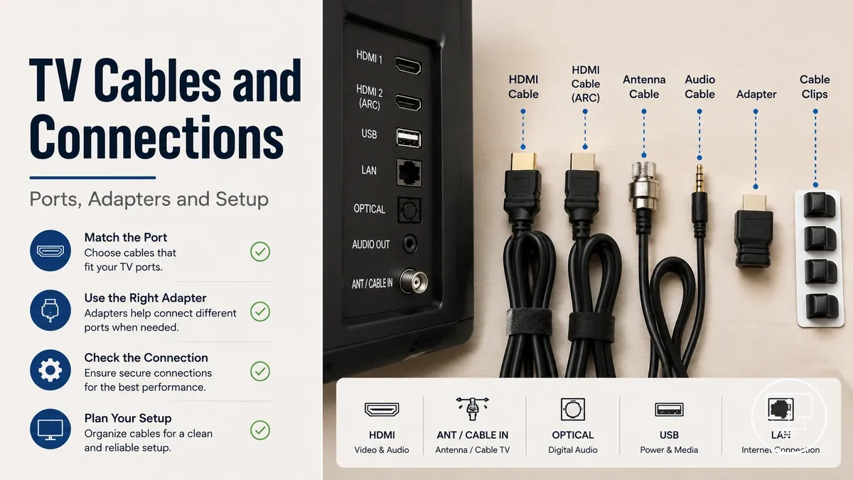
TV cables and connection accessories are components used to link a television with external devices and signal sources including media players, antennas, and audio systems. They include HDMI cable, antenna cable, optical audio cable, connectors, adapters, splitters, and extenders that control how signal, audio, and video move between devices. The way these parts are selected and combined directly affects picture quality, sound delivery, and overall setup outcome in a TV setup environment.
Choosing between different TV cables and connection accessories depends on multiple variables such as TV ports, device inputs, cable type, connector fit, cable length, signal condition, and compatibility. A key distinction exists between physical fit and signal capability, where a cable may connect properly but still not support the required audio or video signal. These conditions vary by device model, room layout, cable condition, and connection requirements.
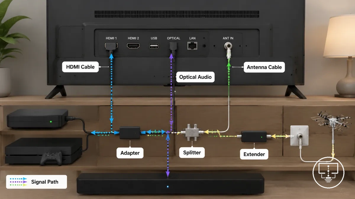
In practical setups, different situations create different connection needs, such as matching HDMI ports for streaming devices, using antenna cables for broadcast signals, or applying optical audio cables for external sound systems. Distance between devices, limited port access, and multi-device configurations may require adapters, splitters, or extenders to maintain a stable signal path and functional routing.
The selection of TV cables and connection accessories is therefore based on structured criteria rather than single-component choices, and each connection type serves a specific role within the overall setup. Detailed examples of cable types, connectors, and use cases are introduced after understanding these foundational selection and compatibility factors.
What TV cables and connection accessories include
TV cables and connection accessories are physical connection parts used to carry or route signal paths between a television and external devices. They define how audio, video, and device connections move through a TV setup through structured cable and port relationships.
These TV cables and connection accessories differ by how they manage signal paths, where cables focus on carrying audio and video while other parts adjust how devices connect through ports and outputs.
Within broader TV setup accessories, these components form the core signal pathway layer that connects devices to the television without handling power delivery or structural setup functions.
- TV cables such as HDMI cable and antenna cable that carry audio and video signals
- Connectors that physically match cable ends to device ports and outputs
- Adapters that adjust connection compatibility between different port types
- Splitters that divide a single signal path into multiple outputs
- Extenders that increase cable reach between devices and TV ports
These TV cables and connection accessories manage signal routing through different roles, where some elements maintain direct audio and video transmission while others adjust fit, distribution, or reach across device connection setups. This category is distinct from power accessories, which relate to energy delivery and control functions rather than signal path transmission for audio, video, and device connections.
TV ports, cable names, and connector differences
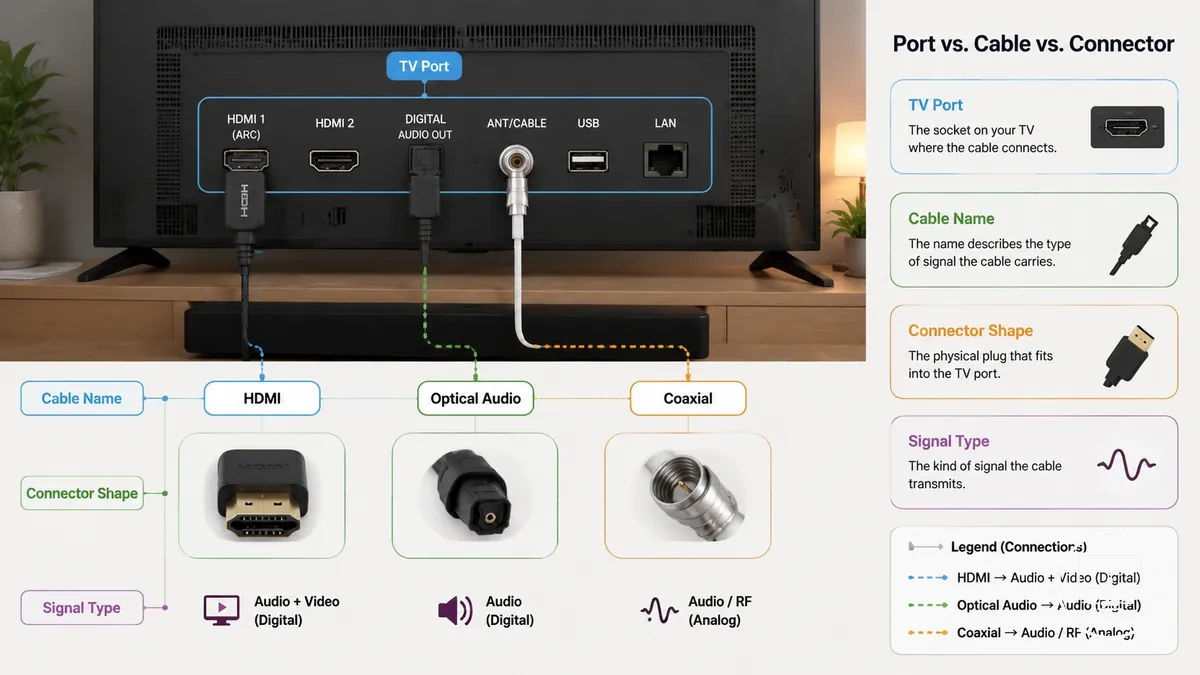
TV ports, cable names, and connector differences describe how the TV-side sockets, cable identities, and plug shapes work together in a device connection. A TV port is the input or output on the television, a connector is the physical plug end, and a cable name often reflects the signal type such as audio, video, or combined transmission. The key distinction is that ports belong to the TV, connectors belong to the cable, and cable names describe signal purpose.
These elements vary by signal type, device design, and compatibility needs in different TV setups. HDMI typically carries combined audio and video, coaxial supports antenna or tuner input signals, and optical audio transmits digital sound to external systems. The connector shape alone does not confirm full capability, so matching depends on both port support and signal type compatibility.
To organize these relationships clearly, the table below groups TV ports by connector type, signal type, and common usage in a TV setup.
| TV Port | Cable Name | Signal Type | Common Use |
|---|---|---|---|
| HDMI port | HDMI cable | Audio and video | Streaming devices and media players |
| Coaxial input | Coaxial or antenna cable | Broadcast signal | TV antenna or tuner connection |
| Optical audio port | Optical audio cable | Digital audio | External speakers or sound systems |
These differences help separate physical connector fit from signal compatibility, where a matching plug shape may still require correct signal support between devices and TV ports.
Main cable types used in TV connections
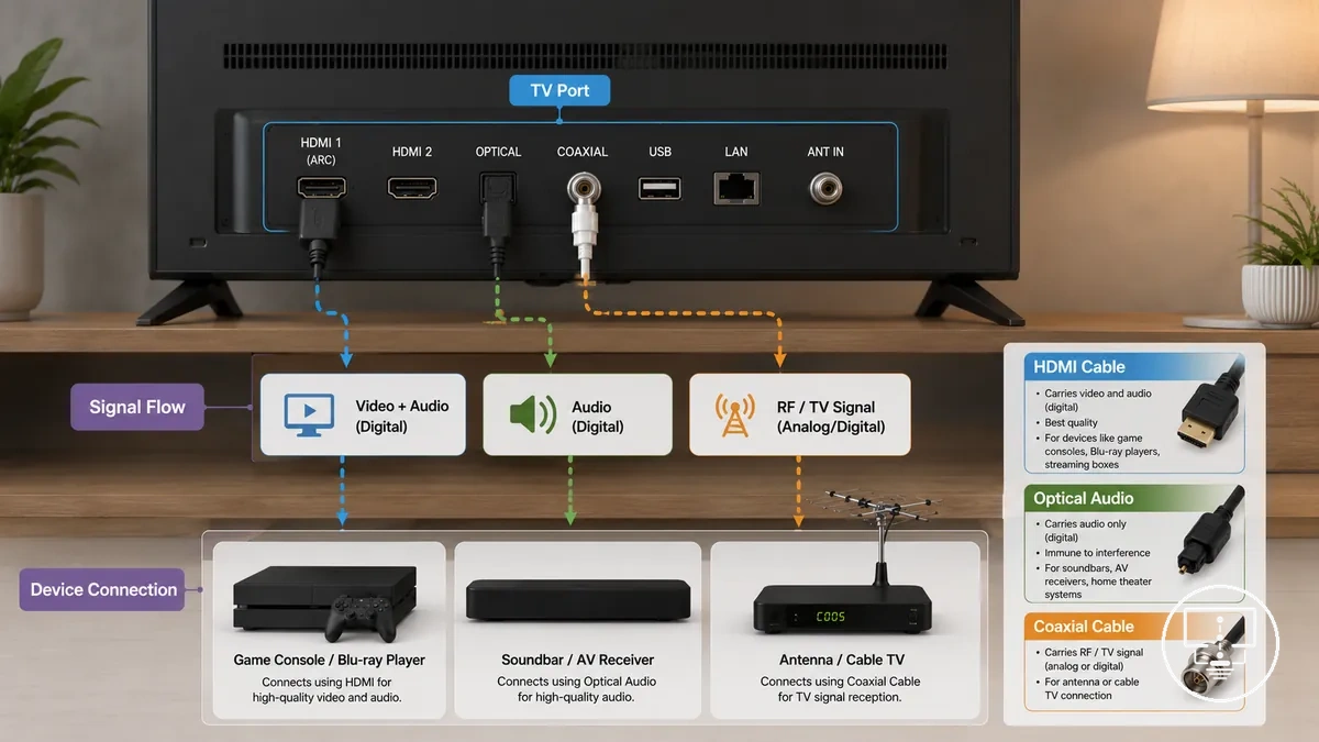
Main cable types used in TV connections refer to TV cable categories that carry video, audio, antenna signal, and device communication between a TV port and external systems. Each TV cable works as a connection part where signal type, connector, and compatibility define how the use case behaves across different devices, making the role of each cable dependent on the port and signal requirements.
These TV cable types are grouped by function and signal behavior. HDMI cable carries combined audio and video signals through a single connector, coaxial cable handles antenna or tuner-based signal input, and optical audio cable transmits digital sound to external audio systems. In some setups, an adapter or accessory is used when a port and connector do not directly align, which can introduce compatibility limits depending on the device context.
Main cable types used in TV connections differ by signal role and device requirement. The table below organizes TV cable types by function, signal behavior, and usage condition to clarify how each cable supports a specific setup context.
| TV Cable Type | Signal or Function | Condition or Device Need | Setup Effect or Limitation |
|---|---|---|---|
| HDMI cable | Audio and video signal | Requires matching HDMI port on TV and device | May not work if port version or support differs |
| Coaxial cable | Antenna or broadcast signal | Needs TV tuner or antenna input port | Signal quality depends on reception conditions |
| Optical audio cable | Digital audio signal | Requires optical audio output/input support | Audio only, no video transmission |
| Antenna cable | Terrestrial TV signal | Depends on available broadcast signal and tuner | Limited by signal strength and location |
These main cable types define how TV connections are structured, where compatibility depends on matching the correct cable, connector, and signal type to the available TV port and device requirement.
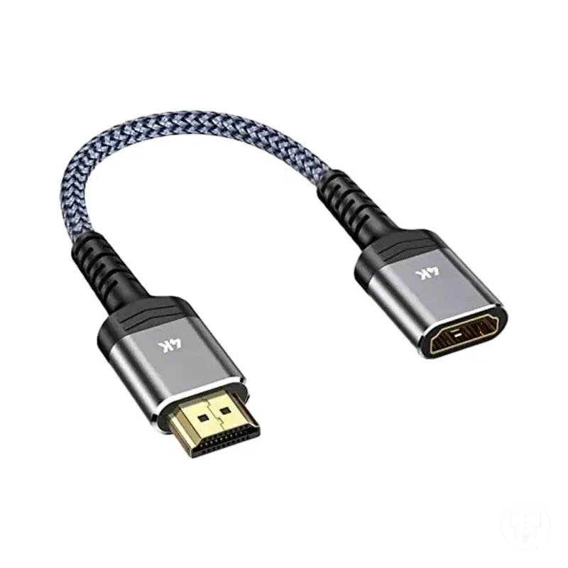
HDMI cables for video and audio
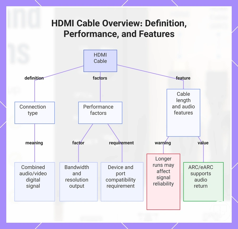
HDMI cable is a TV cable that carries video and audio between a device and a TV port through a single digital connection. It is used where an HDMI port on a device and display handles both signals together, making it a combined connection type within common TV setups.
HDMI cable performance depends on bandwidth, device support, and the specific HDMI port configuration. Resolution output, audio behavior through ARC or eARC, and overall signal handling can vary depending on device capability and port support. Cable length may also influence stability in some setups, especially where longer routing or tighter installation space is involved.
- Bandwidth: affects video and audio data capacity through the HDMI cable
- ARC and eARC: supports audio return from TV to external sound devices through HDMI
- Cable length: longer HDMI cable runs may affect signal reliability depending on setup conditions
- Resolution support: depends on device and HDMI port capability for video output
- Device and port compatibility: requires matching HDMI cable with supported HDMI port
This chart shows what an HDMI cable is, its performance factors such as bandwidth and device compatibility, and features including cable length and ARC/eARC.
Coaxial and antenna cables for TV signal
Coaxial cable and antenna cable are TV cable types used to carry television signal from a wall plate, antenna point, or tuner into the TV system through a shielded connection path. They are designed to maintain signal stability between the signal source and the TV input, making them distinct from device-to-device audio or video cables that handle active media transmission.
Signal performance in coaxial cable and antenna cable depends on cable condition, connector fit, and shielding quality along the signal path. A secure connection at the F-type connector and wall plate supports stable signal flow into the tuner, while a loose connector or worn shielding can increase signal loss or reduce reception consistency. Cable length and routing may also influence signal quality depending on installation constraints and surrounding interference conditions.
- Connector fit: secure connection between F-type connector, wall plate, and tuner input
- Cable condition: checks for wear, damage, or degradation along the coaxial cable
- Shielding quality: evaluates protection against external signal interference
- Signal path continuity: confirms uninterrupted flow from antenna point to TV input
- Wall point contact: ensures stable interface between antenna cable and wall socket
Optical audio cables for external sound
Optical audio cable is a digital audio-only connection used to transmit sound from a TV optical port to external devices such as a soundbar or receiver. It carries digital audio without video, which makes it distinct from HDMI audio paths that can combine video and audio within one connection.
Optical audio cable performance depends on device support, optical port availability, and the audio format limitations between the TV and external sound system. A soundbar or receiver may output sound differently depending on supported digital audio formats, while HDMI audio or ARC can sometimes provide broader audio handling. This creates a limitation where optical connections remain focused on audio transfer and depend on compatible device support rather than universal audio functionality.
- Optical port availability on TV, soundbar, or receiver
- Digital audio transmission only (no video support)
- Device support for optical input/output formats
- Comparison boundary with HDMI audio and ARC-based connections
- Sound output behavior depends on connected device capability
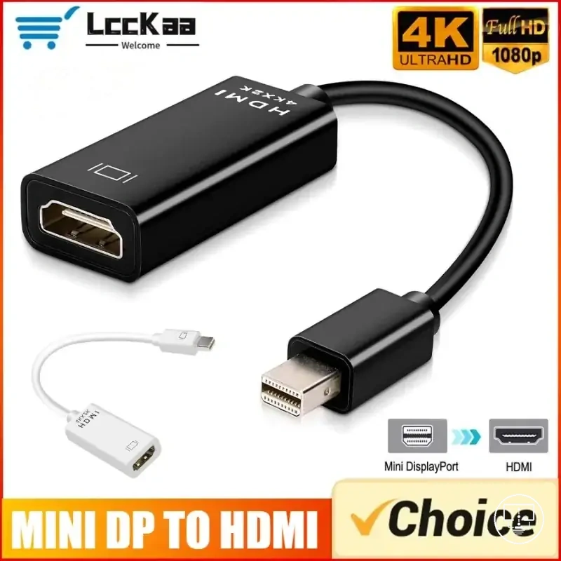
TV connectors, adapters, splitters, and extenders
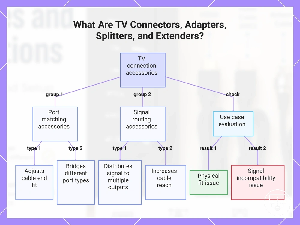
TV connectors, adapters, splitters, and extenders are connection accessory types used with a TV cable to adjust how a signal moves between a port and a device based on port compatibility and use case requirements. They modify fit, direction, reach, or routing without replacing the core cable type, which makes them distinct from the main signal-carrying cable itself within a TV setup.
These accessories work under different use case conditions depending on compatibility and physical constraints. A connector may help align a cable to a specific port shape, an adapter may bridge different port types, a splitter may distribute one signal to multiple outputs, and an extender may increase reach between devices. Their effectiveness depends on correct port matching, signal compatibility, and device support, and they may solve physical limitations such as tight space or short cable length but cannot resolve incompatible signal types between devices.
TV connectors, adapters, splitters, and extenders can be grouped based on the connection problem they are designed to address.
- Connector: adjusts physical cable end fit to match a specific port
- Adapter: bridges different port types while depending on signal compatibility
- Splitter: distributes a single signal to multiple connected devices
- Extender: increases cable reach when device distance creates a limitation
- Use case check: evaluates whether the issue is physical fit or signal incompatibility
This chart groups TV connection accessories by function and shows a use case check to identify whether the issue is physical fit or signal incompatibility.
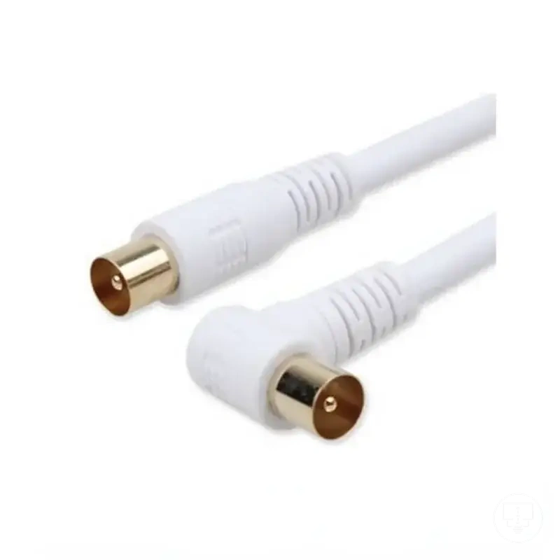
F-type and coaxial connectors
F-type connector is a threaded connector used with coaxial cable and antenna cable to join a wall plate or antenna point to a TV tuner input. It defines the physical cable end interface where the coaxial cable meets the wall socket, making it a key fit point for maintaining stable signal flow through shielding in TV antenna setups. The main distinction is its role in controlling the quality of contact at the wall plate connection rather than changing the signal type itself.
F-type connector and coaxial connector behavior depends on thread engagement, cable end condition, and wall socket quality along the signal path. A secure screw-on connection helps maintain stable reception, while a loose connector or damaged cable end can weaken signal continuity and affect tuner reception. In some cases, wall plate wear or poor contact alignment may also contribute to unstable signal delivery.
- Connector fit: secure alignment between F-type connector and wall plate
- Screw-on connection: threaded locking to stabilize coaxial cable attachment
- Cable-end condition: wear or deformation affecting contact stability
- Wall socket condition: interface quality at the antenna wall plate
- Reception risk: signal instability when connection is loose or degraded
Right angle HDMI adapters for tight spaces
Right angle HDMI adapter is a physical-fit accessory used to redirect an HDMI cable at a 90-degree angle when connecting in tight space conditions behind or beside a TV. It depends on port orientation and wall clearance, where the available space around the HDMI port determines whether the angled direction reduces strain or creates obstruction. The main distinction is that it changes cable direction for fit, not signal behavior.
Right angle HDMI adapters for tight spaces depend on adapter angle, port position, and cable direction relative to the TV layout. In cramped rear setups, bend relief can improve because the HDMI cable is no longer forced to bend sharply at the port, but incorrect angle selection may still cause obstruction or poor clearance near walls or mounting surfaces. Fit is therefore conditional on spatial layout rather than a universal configuration.
Right angle HDMI adapters for tight spaces can be assessed using a simple fit checklist focused on clearance and obstruction risk.
- Adapter angle aligns with HDMI port orientation on the device
- Wall clearance allows the HDMI cable to sit without pressure
- Cable direction avoids sharp bends after connection
- Bend relief is maintained at the port connection point
- No obstruction from wall, mount, or adjacent ports
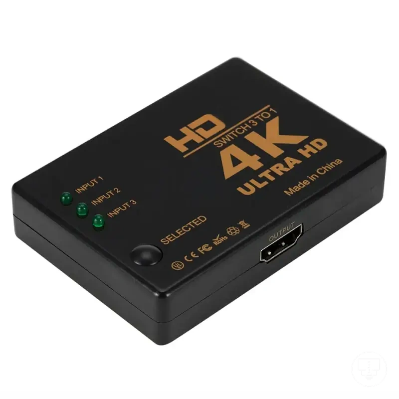
Splitters, couplers, and extension cables
Splitter is a signal routing accessory that divides one TV cable signal into multiple outputs, coupler is a connector that joins two cable ends into a continuous path, and extension cable is used to lengthen an existing connection between a TV port and a device. Each one changes the cable path in a different way, where the main distinction is that splitters divide, couplers join, and extension cables lengthen the connection.
Comparison: Splitter divides signal routing across multiple devices, coupler joins two cable ends into one continuous signal path, and extension cable increases cable length between devices and TV ports. These functions affect device count, cable length, and signal routing structure, and performance can vary depending on whether the setup is passive or powered. In many cases, passive configurations may introduce signal loss when the load increases or cable runs become longer, while powered setups may handle distribution differently depending on device support and signal type.
Cable length, clearance, and signal requirements
Cable suitability depends on cable length, clearance around the installation area, and signal requirement of the connected devices. These criteria determine whether a cable or accessory fits physically and whether it can maintain stable signal transmission under required resolution and bandwidth conditions. The main distinction is between physical fit constraints and signal capability constraints. :contentReference[oaicite:0]{index=0}
Cable length affects reach between devices and TV ports, while clearance and bend radius influence how safely the cable routes through tight spaces without strain. Shielding and bandwidth determine how well the signal path handles interference and resolution demands, especially where signal loss risk increases across longer or less protected runs. In many cases, performance depends on the combined effect of these factors rather than a single attribute.
Evaluation separates physical fit issues from signal-capability issues. Physical issues include limited clearance, tight bends, or insufficient cable length. Signal issues relate to bandwidth limits, weak shielding, or unstable signal paths affecting resolution. This separation helps identify whether the setup requires adjusted routing space or improved signal capability.
| Criteria | Condition Factor | Physical Impact | Signal Impact | Risk or Limitation |
|---|---|---|---|---|
| Length | Distance between devices | Affects reach and placement flexibility | May influence signal stability in longer runs | Increased signal loss risk over extended cable runs |
| Clearance | Available space around installation | Determines fit and routing space | No direct signal effect | Obstruction or strain from restricted space |
| Bend radius | Cable curvature at connection points | Affects strain on connectors and ports | May affect signal consistency if too tight | Possible signal degradation from excessive bending |
| Shielding | Cable construction quality | No physical placement effect | Reduces interference on signal path | Higher noise or instability in weak shielding |
| Bandwidth | Device and cable capability match | No physical effect | Determines resolution and data capacity | Reduced performance if insufficient for required signal |
Cable distance, bend direction, and wall clearance
Cable distance, bend direction, and wall clearance are sizing factors that determine whether a cable can reach a TV port and sit safely in the available space. These factors define cable length needs, clearance around the back of the TV, and bend radius limits that affect fit and strain at connection points. The main distinction is between reach capability and safe physical routing under signal requirement conditions that may also affect signal loss and resolution stability. :contentReference[oaicite:0]{index=0}
Cable route, measured distance, and port side position influence whether the setup meets physical fit requirements without stressing the cable or connectors. Tight wall gaps can force sharper bends that reduce safe bend radius and increase strain on the connection, while insufficient cable length can limit reach even when signal requirement and bandwidth support higher resolution output. Cable distance, bend direction, and wall clearance determine fit conditions and help identify whether adjustments are needed before installation.
Checklist for Cable distance, bend direction, and wall clearance helps verify routing accuracy, physical clearance, and strain risk before final placement.
- Cable route aligns with measured distance between device and TV port
- Bend direction maintains safe bend radius without sharp strain points
- Wall gap provides enough clearance behind or beside the TV
- Port side position matches intended cable entry direction
- Strain relief is maintained at connection points to reduce stress
- Overall fit supports stable routing without forcing cable compression
For broader routing decisions and placement adjustments, this setup can be extended using manage TV cables guidance when space constraints or routing limitations affect fit.
Resolution, bandwidth, and signal loss conditions
Resolution, bandwidth, and signal loss conditions determine whether a cable can carry the required picture, sound, or broadcast signal across the signal path between devices and TV ports. These factors go beyond physical fit and define whether the connection can meet the signal requirement for stable resolution output and audio transmission. The main distinction is between a cable that fits the port and a cable that supports the required signal performance. :contentReference[oaicite:0]{index=0}
Signal capability depends on resolution demand, bandwidth capacity, cable length, shielding quality, and overall cable condition. Even when a cable connects correctly, limitations in signal path quality or increased signal loss can reduce stability. Device compatibility and signal requirement also influence whether the connection maintains consistent output under real usage conditions.
Criteria overview: Resolution, bandwidth, and signal loss conditions define compatibility behavior, while cable condition, shielding, and length determine how reliably the signal is maintained or degraded across the connection path.
| Criteria | Condition Factor | Physical Fit Role | Signal Capability Role | Risk or Outcome |
|---|---|---|---|---|
| Resolution | Display and source requirement | No direct effect | Defines required signal detail level | Mismatch may reduce image clarity |
| Bandwidth | Data transmission capacity | No physical effect | Controls supported data rate | Insufficient bandwidth may limit performance |
| Signal loss | Cable length and condition | No physical effect | Affects stability of transmitted signal | Higher loss may reduce reliability |
| Shielding | Cable construction quality | No direct effect | Reduces interference in signal path | Poor shielding may increase noise risk |
How to match cables to TVs, devices, and connection needs
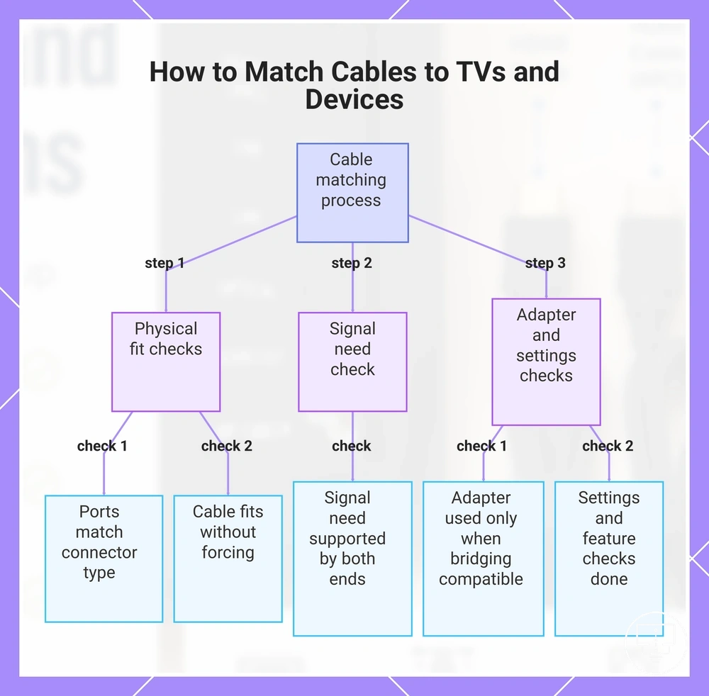
How to match cables to TVs, devices, and connection needs depends on aligning the TV port, device port, cable connector, and signal need before confirming compatibility. The key point is that physical connection alone is not enough, because compatibility also depends on whether the signal requirement is supported across both ends.
The matching process also depends on device capability, supported signal type, and whether an adapter is needed to bridge different ports. Even when the cable connector fits both the TV port and device port, settings or an unsupported feature can still block proper output, which means compatibility must be confirmed beyond the physical fit stage.
Step check: How to match cables to TVs, devices, and connection needs can be verified using the steps below, which organize TV port, device port, cable connector, signal need, and compatibility outcome.
- TV port matches the required cable connector type
- Device port supports the same connection format
- Cable connector fits both ends without forcing alignment
- Signal need is supported by both device and TV capability
- Adapter is used only when compatibility allows bridging
- Settings and unsupported feature checks are completed before use
For broader evaluation of connection compatibility, confirm both physical fit and signal support before final use of any cable or accessory.
This chart shows the step-by-step checks for cable matching, covering physical port compatibility, signal support, and adapter or settings verification.
When to choose a cable, adapter, connector, or splitter
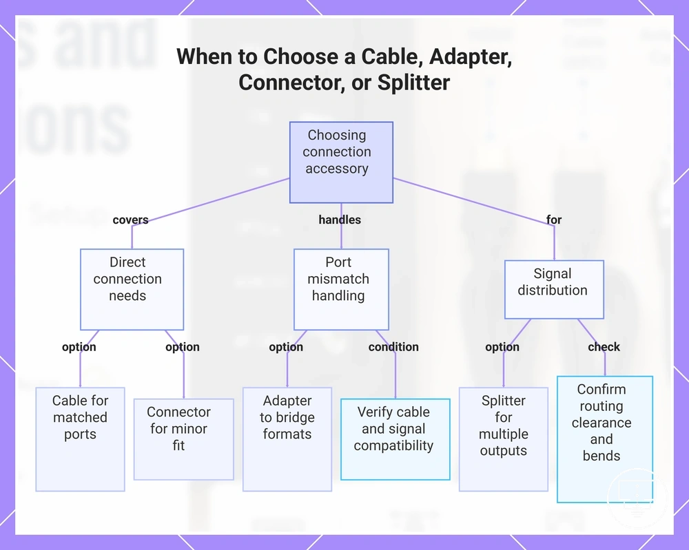
Choosing a cable, adapter, connector, or splitter depends on reach, fit, routing, port mismatch, and signal distribution needs. The decision starts by checking whether the TV port and device port align physically and functionally. It then moves to how the signal need is handled across the setup. This creates a clear decision frame based on compatibility and layout constraints.
Each option serves a different role in the connection structure. A cable is used when reach and direct fit already match between devices. A connector supports basic alignment adjustments without changing signal behavior. An adapter handles port mismatch when different formats must be bridged, while a splitter is used for signal distribution to multiple outputs. The correct choice depends on whether the limitation is physical routing or signal structure.
When to choose a cable, adapter, connector, or splitter can be organized through a decision checklist that separates fit, routing, and signal distribution requirements.
- Cable: use when TV port and device port match and reach is sufficient
- Adapter: use when port mismatch exists but signal compatibility is supported
- Connector: use when minor fit adjustment is needed without changing signal type
- Splitter: use when signal distribution is required for multiple devices
- Routing check: confirm clearance and bend constraints before final selection
Adapter selection should only be considered when both cable type and signal need are already compatible, and only the port mismatch prevents connection. In cases where settings or unsupported feature limitations exist, even a correct adapter may not resolve the connection requirement, so the condition must be verified before selection.
Physical constraints and signal requirements can overlap in real setups. Reach, fit, routing, and signal distribution may interact differently depending on device design and port layout. This means the final decision should always confirm both connection structure and signal need before choosing the accessory type.
In practical selection, the simplest solution that satisfies compatibility should be chosen first, then expanded only when routing or signal distribution requires it. This keeps the setup aligned with actual connection needs rather than unnecessary complexity.
The products below are useful examples for comparing available options. Before buying, check that the compatibility criteria, key features, and product details match your needs.
This chart organizes the decision framework for selecting the correct connection accessory based on port compatibility, signal need, and physical routing.
Cable-related TV connection problems
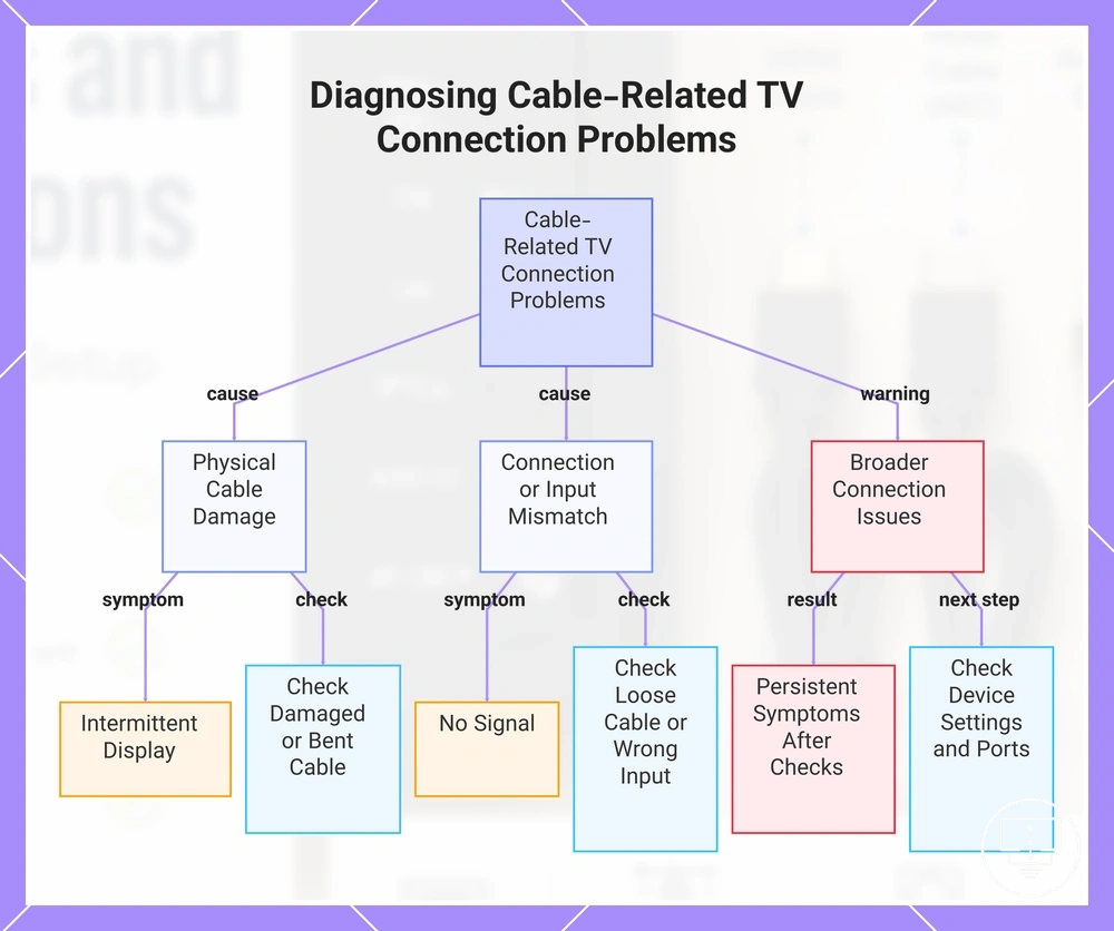
Cable-related TV connection problems usually show up through symptom signals like no signal, wrong input, loose cable, damaged cable, bent cable, incompatible cable, or antenna connection failure. These symptoms often indicate a cable condition issue or signal path interruption, but they may also overlap with source device or TV settings, which is the key distinction in diagnosis.
When a no signal issue appears, a loose cable or wrong input selection is often involved. A damaged cable or bent cable may cause intermittent signal problems or unstable picture output. An incompatible cable can prevent proper signal recognition between device and TV. In some cases, antenna connection issues may also mimic cable faults, so a check of both physical connection and input settings is needed before assuming a cable problem.
Diagnostic checklist: Cable-related TV connection problems can be checked by matching symptom, cable condition, and outcome to narrow down likely causes.
- Symptom: no signal → check loose cable or wrong input
- Symptom: intermittent display → check damaged cable or bent cable
- Symptom: no antenna reception → check antenna connection and cable path
- Symptom: no device detection → check incompatible cable
- Symptom: unstable picture → check loose connector or signal path issue
If symptoms persist after checking cable condition, ports, and input selection, the issue may extend beyond cables into broader connection problems involving device settings, ports, or multiple accessory interactions.
This chart maps common cable-related TV connection symptoms to their likely causes and recommended checks, including a warning about broader issues.
Loose, damaged, bent, or incompatible cables
Loose cable, damaged cable, bent cable, or incompatible cable issues can interrupt video, audio, or antenna connection and often appear as a symptom such as no signal or unstable output. These conditions usually affect the physical signal path first, which is why visible cable condition and connector fit should be checked before assuming device failure.
A loose cable can create intermittent no signal behavior, while a bent cable may gradually weaken signal flow over time. A damaged cable or broken cable end can stop transmission completely, and an incompatible cable may prevent correct signal recognition between device and TV. In antenna connection setups, even small looseness can affect reception stability, so a careful check of both ends is important before deeper diagnosis.
- Loose cable → symptom: no signal or unstable picture → check connector tightness at both ends
- Bent cable → symptom: intermittent signal → check cable routing and strain points
- Damaged cable → symptom: no audio/video → check for visible cuts or breaks
- Incompatible cable → symptom: no device recognition → check cable type match with ports
- Broken cable end → symptom: signal loss → check connector integrity and fit
No signal, wrong input, and failed antenna connections
When no signal occurs, wrong input or a failed antenna connection may be the cause, but a loose cable, damaged cable, bent cable, or incompatible cable in the cable connection path can also trigger the same symptom. The issue should be treated as a signal path problem where TV input, source output, and antenna connection must all be checked before assuming failure. The main distinction is that no signal can come from either wrong input selection or a cable condition issue. :contentReference[oaicite:0]{index=0}
These problems depend on how the source device, TV input, and antenna connection align across the signal path. A wrong input is a clear configuration issue that can show a no signal symptom even when the cable connection is intact. A failed antenna connection may reflect weak or interrupted reception, while a loose cable or damaged cable can physically break signal transmission. In some cases, an incompatible cable or bent cable may reduce or block signal flow, so each condition must be checked step by step to identify the outcome.
- Symptom: no signal → check wrong input and source device selection
- Symptom: no signal persists → check loose cable and damaged cable at both ends
- Symptom: weak or missing antenna signal → check antenna connection stability
- Symptom: intermittent signal → check bent cable or signal path strain
- Symptom: no detection → check incompatible cable and cable connection type
In most cases, isolating the symptom through a check of input, cable connection, and antenna connection helps narrow down whether the issue is caused by wrong input or a physical cable fault, rather than assuming a single failure point.