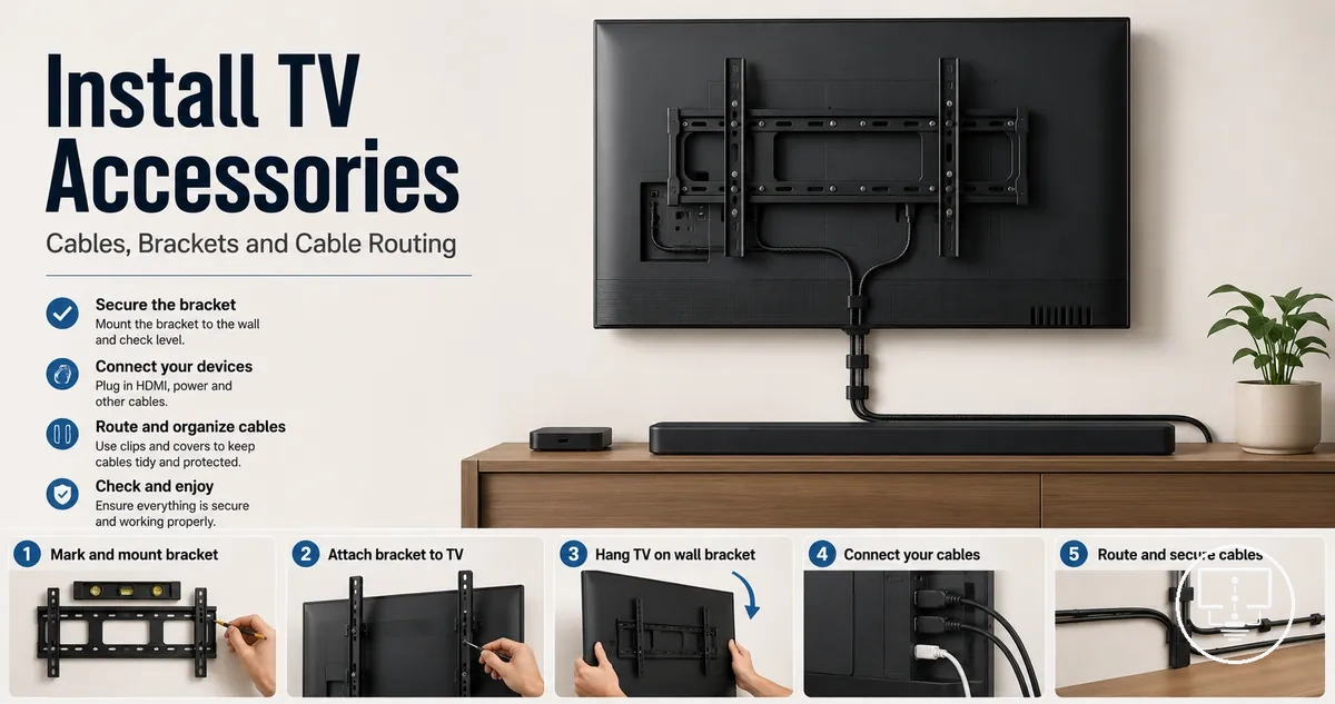
Installing TV Setup Accessories
Installing TV setup accessories starts with preparing the TV area before any accessory is fitted, connected, routed, or checked. The installation depends on the TV, the wall or stand, the accessory type, and the cable route.
A wall-mounted setup usually needs mounting hardware, support checks, setup tools, port access, and a planned cable path before the TV is fixed in place. A stand-mounted setup may focus more on placement accessories, connection cables, cable management, and stable access behind the screen. A cable-led setup can depend on where HDMI, power, audio, and antenna connections sit, so preparation should stay separate from execution.
Skipped checks can create rework, blocked ports, strained cables, or unsafe fitting. Mounting hardware may not suit every wall type, and connection cables may not route cleanly behind every TV position. Cable management can also limit future access if clips, covers, or cable routing parts are fixed too early. The main installation groups are mounting, connection, cable management, and final checks.
Safe installation means fitting accessories only after the main conditions are clear. Safety checks should confirm stability, port access, cable signal, ventilation, and future access. This opening frames installation guidance only; full buying, troubleshooting, and compatibility details may vary by TV model, mounting surface, room layout, and setup configuration.
TV Setup Accessories That Need Installation
TV Setup Accessories That Need Installation are setup parts that require physical fitting, routing, fastening, or placement before the TV setup is complete. Unlike accessories that are simply plugged in, these items become part of the installation environment and can affect support, cable routing, or access. This distinction separates physical installation from simple connection.
TV setup accessories are often grouped by installation role rather than by product type. Different accessory groups support mounting, cable routing, connection access, or setup preparation, and installation effort can vary by accessory type and setup conditions. Related TV setup accessories may serve different installation roles within the same setup.
TV Setup Accessories That Need Installation can be organized by installation role because accessory type often changes the amount of physical fitting required.
- Mounting brackets, spacers, and screws: Fitted to secure or position the TV; the main condition depends on support requirements and mounting location.
- Cable clips and cable routing items: Attached to guide or hold cables; the main condition depends on the cable route and future access needs.
- Wall covers and pass-through kits: Installed to manage cable entry and exit points; the main condition depends on surface layout and cable path design.
- HDMI cables and adapters: Connected to provide signal paths and port access; the main condition depends on connection points and available routing space.
- Power accessories and setup tools: Positioned or used during installation; the main condition depends on setup arrangement and installation tasks.
In a wall-mounted setup, mounting parts, cable clips, and wall covers often involve more physical fitting than in a table-based arrangement. A table placement setup may rely more on positioning accessories and maintaining port access, while cable routing projects can increase installation effort even when the TV location stays the same. Compatibility, checklist, and troubleshooting details are included only where they affect installation sequence or safety, keeping this section focused on installation-relevant roles.
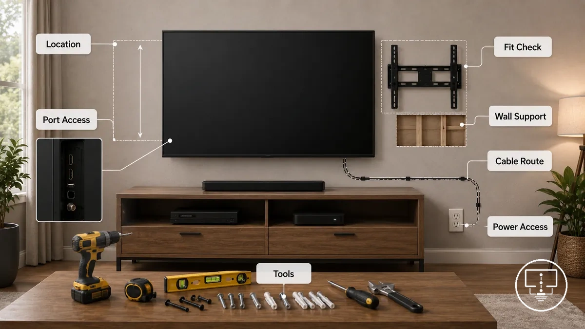
Pre-Installation Checks for Location, Fit, and Tools
Pre-installation checks should confirm that the installation area, accessories, and required tools are suitable before work begins. Checking location, fit, port access, cable route, wall support, accessory compatibility, and power access can reduce fit problems, cable strain, and unnecessary rework. These checks come before attaching or routing accessories.
Missed setup checks can lead to fit problems, blocked connections, cable strain, or installation delays. Reviewing conditions before installation can help identify issues earlier and reduce rework. For a broader pre-installation checklist, use the same condition-based approach before selecting installation steps.
Pre-Installation Checks for Location, Fit, and Tools verify whether the installation environment supports the planned setup and help identify risks before accessories are attached or routed.
- Location: Check that the planned position supports viewing, access, and installation needs; poor placement can increase rework.
- TV size and fit: Check that accessory dimensions and support points align with the TV; a mismatch can create fitting issues.
- Port access: Check that ports remain reachable after installation; restricted access can complicate future connections.
- Wall support or furniture support: Check that the mounting surface or furniture suits the planned setup; unsuitable support can affect installation stability.
- Accessory compatibility: Check that setup parts match the planned configuration; compatibility differences can affect fit.
- Cable route: Check the cable path before routing; tight bends or blocked paths can create cable strain.
- Tools: Check that required tools are available before starting; missing tools can interrupt installation.
- Screws and anchors: Check that screw type and anchor suitability match the installation surface; incorrect hardware can affect attachment.
- Power access: Check that power connections remain accessible after installation; limited access can complicate setup changes.
For wall-mounted setups, wall support, anchors, and cable routing conditions may have a greater effect on installation decisions. Stand-mounted setups often depend more on furniture support, placement space, and port access. Renter-friendly setups may rely on removable routing methods and surface limits rather than permanent attachment points. The installation approach should follow the conditions identified during the checks.
Stop and verify any uncertain fit, hardware choice, or tool requirement before continuing. Local checks that follow can help confirm installation conditions in more detail.
Wall Type, Stud Position, and Mounting Surface
Wall type, stud position, and mounting surface directly affect whether screws, anchors, brackets, and support accessories may be suitable for installation. Different wall surfaces can require different fixing methods, and support points influence where hardware can be placed. The main condition to verify is the surface condition and available support behind the mounting area.
Wall Type, Stud Position, and Mounting Surface checks help verify whether support points and fixing locations are suitable before installation and help identify local support risks.
- Drywall: Check stud position and support points; missed support locations can increase anchor type and support risk.
- Stud position: Check bracket alignment and screw placement; poor alignment may affect support.
- Masonry: Check drill suitability and surface condition; unsuitable drilling methods may affect anchor performance.
- Cabinet surfaces: Check the mounting area and fixing points; weak or damaged surfaces may limit attachment options.
- Anchors and screws: Check that anchor type and screws suit the mounting surface; mismatched hardware can increase support risk.
Wrong anchors or missed studs can create installation problems and may lead to rework. If anchor suitability, stud position, or surface condition remains uncertain, stop and recheck the mounting surface before continuing.
For rented spaces, uncertain wall construction, or unusually heavy screens, support conditions may require additional verification. When wall cavities, hidden materials, or masonry conditions are unclear, a professional check may be appropriate before proceeding.
TV Size, Port Access, and Cable Routes
TV size, port access, and cable routes affect where accessories can be placed before installation starts. A larger screen, tight mount clearance, or rear-facing ports can change how cables, adapters, and mounting parts fit behind the TV. The main fit condition is whether accessory placement leaves enough access for connections and routing.
Blocked ports, tight cable bends, and limited clearance can make a setup harder to connect or adjust after the TV is positioned. Physical fit checks confirm whether accessories can sit in the available space, while connection compatibility checks confirm whether HDMI access, outlet position, and cable routes support the planned setup. Use fit and compatibility checks before fixing accessories in place.
In wall-mounted or multi-device setups, TV Size, Port Access, and Cable Routes checks verify whether the TV shape, connection points, and planned cable path support accessory placement without blocking access.
- TV size: Check screen size and accessory fit; poor clearance can affect placement behind or below the TV.
- Mount clearance: Check the space between the TV and wall or stand; limited clearance can restrict adapters and cable routing.
- VESA spacing: Check mount-related spacing where relevant; mismatched spacing can affect bracket placement.
- Port access: Check side-facing and rear-facing ports; blocked ports can limit HDMI access and future device changes.
- Cable routes: Check cable path, cable bend, and outlet position; tight routing can create strain or make later access harder.
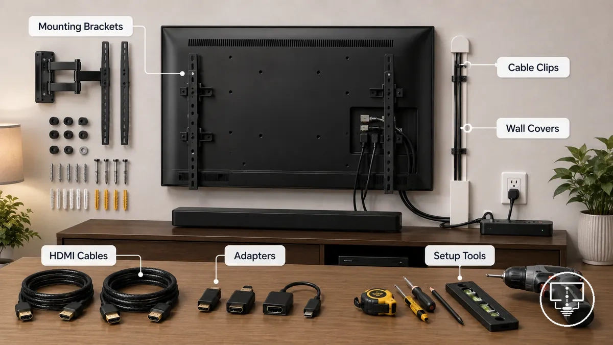
Tools, Screws, Anchors, Clips, and Covers
Tools, screws, anchors, clips, and covers should be matched to the installation role before work begins. A drill, level, tape measure, stud finder, screwdriver, mounting screws, washers, anchors, spacers, cable clips, wall cable covers, and pass-through parts each support a different part of the setup. Separate setup tools from mounting hardware and cable-control parts before installation starts.
Mismatched screws, anchors, or clips can interrupt installation or create a poor fit. Supplied hardware should still be checked against the TV, surface, and accessory role because included parts may not suit every condition. If hardware is missing, mismatched, or uncertain, stop and check before attaching anything.
Tools, Screws, Anchors, Clips, and Covers can be grouped by part purpose so each item is matched to its role, condition, and stop signal.
- Setup tools: Use a screwdriver, drill, level, tape measure, or stud finder to measure, align, and prepare the fixing area; stop if the tool needed for the surface or accessory is not available.
- Mounting screws and washers: Use screws and washers to fasten brackets or support accessories; stop if screw length, thread fit, or washer placement is uncertain.
- Anchors and spacers: Use anchors and spacers when the surface or TV position requires extra support or clearance; stop if anchor suitability or spacer fit is unclear.
- Cable clips: Use clips to guide visible cable paths; stop if the clip type, surface hold, or cable route may create strain.
- Wall covers and pass-through parts: Use covers and pass-through parts to organize cable-control sections; stop if the route, surface opening, or future access is uncertain.
For a wall mount, fastening parts usually need the closest match to the surface and bracket role. For cable covers or pass-through parts, the fit condition depends more on cable path, surface limits, and access after installation.
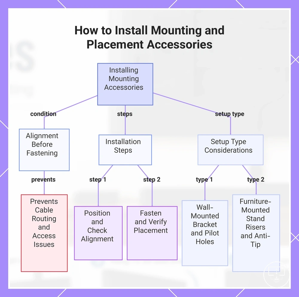
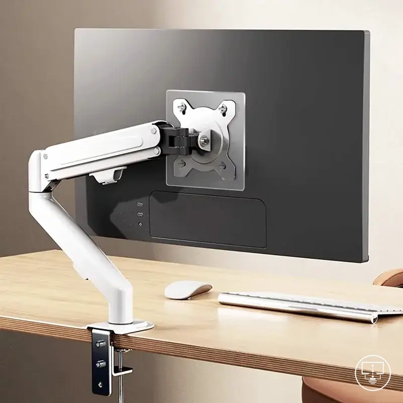
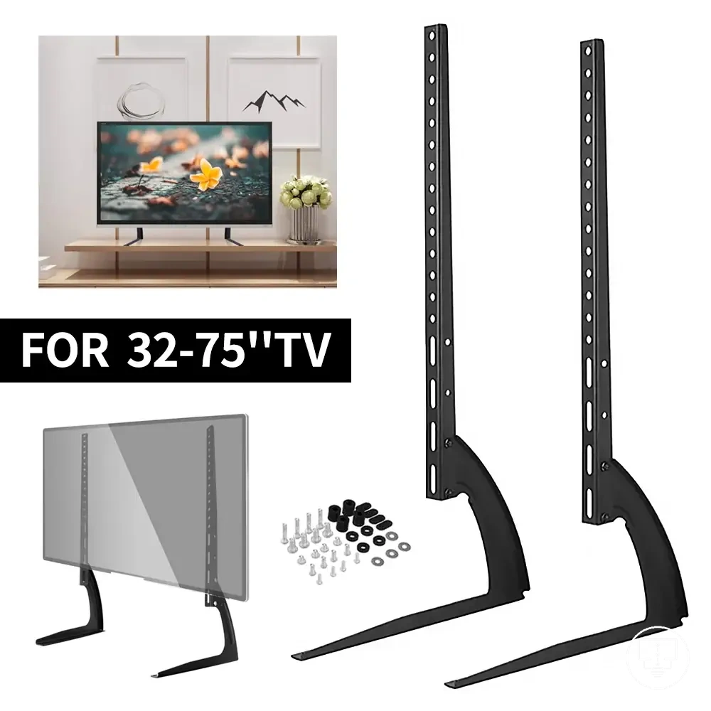
Installing Mounting and Placement Accessories
Installing mounting and placement accessories starts with positioning support components before cables are tightened, concealed, or routed. Mounting accessories, placement accessories, bracket placement parts, spacers, and anti-tip accessories should be aligned with the TV location and support surface before fastening begins. Alignment before fastening is the key condition.
Incorrect placement can make later cable routing, port access, or adjustment more difficult. Positioning accessories should be checked before cables are secured because limited movement after fastening may affect access and clearance. For broader setup differences beyond installation-focused tasks, see mounting accessories.
In wall-mounted setups, bracket placement, pilot holes, and wall condition often influence installation decisions. In furniture-mounted setups, stand risers, anti-tip accessories, stability, and ventilation clearance may have a greater effect on positioning choices.
Verify placement, clearance, and access before moving to cable installation. Rechecking alignment is usually easier before cables are tightened or hidden.
Installing Mounting and Placement Accessories uses the following steps to organize positioning, fastening, and verification before cable installation begins.
- Position mounting accessories: Place brackets, stand risers, or support accessories in the planned location and verify that the TV position matches the intended viewing area.
- Check bracket placement: Confirm bracket placement aligns with support points and verify that the planned position allows ventilation clearance and port access.
- Prepare pilot holes if required: Mark and prepare pilot holes only when the mounting condition requires them and verify alignment before fastening.
- Fit spacers and mounting screws: Position spacers and mounting screws according to the installation condition and verify that parts sit evenly without forcing alignment.
- Perform level checks: Use level checks before final tightening and verify that the accessory position remains consistent across support points.
- Install anti-tip accessories: Position anti-tip accessories where the setup may benefit from additional restraint and verify that movement remains controlled without blocking access.
- Verify final placement: Confirm ventilation clearance, port access, and accessory alignment before moving to cable installation or cable concealment.
This chart shows the key condition, main installation steps, and setup type considerations for correctly installing TV mounting and placement accessories.
Marking Bracket Position and Drilling Pilot Holes
Marking bracket position and drilling pilot holes starts with confirming the planned height, support points, and level before any fixing holes are made. Hole positions should reflect the room layout, TV size, seating height, and manufacturer instructions where they apply. Drill only after surface and hardware confirmation.
Crooked marks, incorrect hole positions, or missed support points can make bracket placement harder to correct. Hidden wires, pipes, or an uncertain wall cavity can also affect whether drilling should proceed. Caution: verify hidden services and unclear wall cavity conditions before creating pilot holes.
For masonry surfaces or uncertain cavities, the drill bit, surface condition, and support points may need additional verification before drilling begins.
Marking Bracket Position and Drilling Pilot Holes uses the following steps to organize measuring, marking, and drilling before brackets or placement accessories are fixed.
- Measure the bracket position: Measure the intended height based on the room layout and TV size, then verify that the planned position supports viewing and access needs.
- Check the level: Place a level across the planned mounting marks and confirm that the bracket position remains aligned before marking hole positions.
- Identify support points: Locate support points before creating drilling points and verify that the planned fixing holes align with the mounting condition.
- Mark hole positions: Mark hole positions clearly and check that spacing matches the bracket layout and installation requirements.
- Match the drill bit: Select a drill bit that suits the surface and hardware condition, then verify that the drill bit matches the intended pilot holes.
- Drill after confirmation: Create pilot holes only after support points, surface condition, hardware fit, and wall cavity checks have been confirmed.
Choosing Mounting Screws, Washers, Anchors, and Spacers
Choosing mounting screws, washers, anchors, and spacers depends on matching the hardware to the TV, mount, wall, and accessory role. Hardware selection should reflect both the secured part and the receiving surface rather than relying on spare parts or assumptions. The main fit condition is the relationship between mounting hardware attributes and installation conditions.
Incorrect screw length, thread type, spacer depth, or anchor material can create fit and attachment problems. Hardware that suits one wall type or bracket thickness may not suit another condition. If supplied hardware does not match the TV, wall type, bracket thickness, or manufacturer limits, stop and check before continuing.
When supplied hardware does not match the surface or TV requirements, different mounting hardware may be needed if it aligns with the installation conditions and manufacturer limits.
Choosing Mounting Screws, Washers, Anchors, and Spacers compares the key criteria used to evaluate hardware fit and installation decisions.
| Entity/part | Attribute/criterion | Value/condition | Effect/risk/decision |
|---|---|---|---|
| Mounting screws | Screw length and thread type | Depends on TV fit and mounting requirements | Incorrect fit may affect attachment or alignment |
| Washers | Bracket thickness and washer use | May be used when spacing or load distribution is needed | Incorrect use may affect hardware fit |
| Anchors | Anchor material and wall type | Depends on the receiving surface | Mismatched anchors may increase support risk |
| Spacers | Spacer depth | Depends on clearance and mounting conditions | Incorrect spacer depth may affect positioning |
| Bracket and wall conditions | Manufacturer limits and bracket thickness | Depends on surface conditions and hardware match | Mismatch may require hardware re-evaluation |
Securing Accessories Without Blocking Ports or Ventilation
Securing accessories without blocking ports or ventilation starts with fastening components in a way that preserves access and airflow around the TV. Tightening pressure, accessory position, and spacer use should be checked together before hardware is fully secured. The main clearance condition is keeping ports reachable and ventilation gaps open.
Port blockage, excessive tightening, or limited airflow can create installation problems after accessories are fastened. A controlled tightening sequence and cable clearance check can help identify access restrictions before the setup is finalized. Recheck ports, ventilation, and bracket movement before completing the installation.
For slim mounts, right-angle adapters, or recessed and downward-facing ports, clearance may depend on accessory position, spacer use, and available access behind the TV.
Securing Accessories Without Blocking Ports or Ventilation uses the following steps to verify fastening, access, and airflow conditions.
- Follow the tightening sequence: Fasten mounting hardware gradually, check bracket movement, and confirm that alignment remains consistent before final tightening.
- Verify port visibility: Check that ports remain visible and reachable, and confirm that accessories do not restrict future access.
- Check cable clearance: Route connected cables with enough clearance for movement and verify that cable paths are not pinched or strained.
- Review spacer use and ventilation gaps: Confirm that spacer use supports the required clearance and check that airflow paths remain open around the TV.
- Perform a final fit check: Verify screen level, bracket stability, port access, and ventilation conditions before finishing the installation.
The final mini-checklist confirms the local access and airflow points before the secured setup is treated as finished.
- Ports remain accessible.
- Cable clearance is maintained.
- Ventilation gap is visible.
- Bracket movement is checked.
- Screen level is verified.
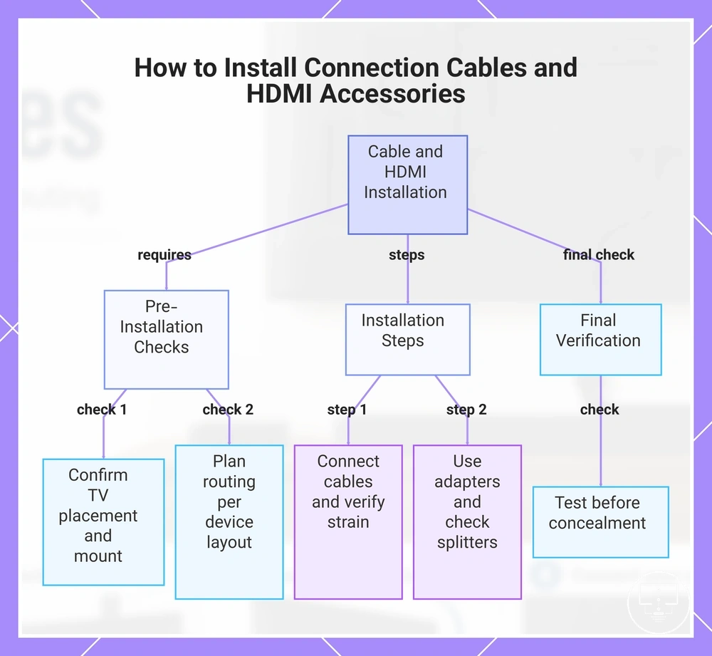
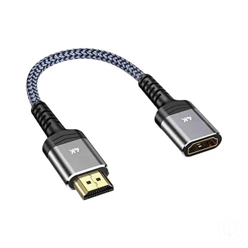
Installing Connection Cables and HDMI Accessories
Installing connection cables and HDMI accessories starts after TV placement, mount position, and access constraints are confirmed. HDMI cables, antenna cables, optical audio connections, power leads, and connector accessories should be routed according to the final device layout rather than before placement decisions are complete. The installation goal is to protect both the signal path and the physical ports.
Port strain, excessive cable length, or restricted device access can create connection problems after installation. A cable run that appears suitable before the TV is positioned may become difficult to access once the setup is complete. The main routing check is whether cables remain connected without unnecessary strain while ports and devices stay accessible.
For wall-mounted setups, cable routing may depend on rear clearance and port location. For stand-mounted setups, cable access is often easier, but cable length and routing still require verification. In multi-device setups, HDMI cables, optical audio connections, and power leads may need additional route planning to preserve device access.
Installing Connection Cables and HDMI Accessories uses the following steps to protect signal paths, reduce port strain, and maintain device access.
- Install HDMI cables: Connect HDMI cables to the intended input, then check that the final cable position does not create port strain after the TV is placed.
- Connect antenna cables: Attach antenna cables according to the planned cable run and perform a connection check to confirm that the signal path remains secure and accessible.
- Install optical audio connections: Connect optical audio cables where required and verify that device access remains available for future adjustments.
- Route power leads: Position power leads according to the device layout and check that cable length does not create unnecessary tension or obstruct access.
- Use right-angle adapters or extensions when needed: In a tight space, a right-angle adapter or extension may help improve cable clearance and reduce port strain when direct routing is limited.
- Check splitters and connector accessories: Where splitters or connector accessories are installed, verify that each connection remains accessible and properly seated.
- Test before concealment: Confirm that connected devices operate as expected before cables are concealed, covered, or routed through permanent cable-control accessories.
This chart shows the key steps and checks for installing connection cables and HDMI accessories to protect signal paths and ports.
Connecting HDMI, Antenna, Audio, and Power Cables
Connecting HDMI, Antenna, Audio, and Power Cables starts with following a clear connection order after device placement is known. HDMI input selection, antenna connection, audio cable placement, and power cable connection should be completed while access remains available behind the TV. Testing should happen before final concealment.
Wrong HDMI input choice, restricted access, or an untested signal can create unnecessary rework after the TV reaches its final position. Checking each cable connection before final positioning can help identify connection issues while ports remain accessible. Perform a signal test before concealing any cables.
For setups with limited rear access, connecting and testing cables before the TV reaches its final position may make later adjustments easier.
Connecting HDMI, Antenna, Audio, and Power Cables uses the following sequence to reduce access issues and prevent avoidable reconnection work.
- Connect HDMI cables: Attach each HDMI cable to the intended HDMI input and verify that the input choice matches the connected device.
- Complete the antenna connection: Connect the antenna cable and check that the cable fit remains secure before final positioning.
- Install the audio cable: Connect the audio cable and verify optical placement or ARC-related placement when those connection methods are used.
- Connect the power cable: Attach the power cable or power lead and maintain separation where needed to preserve safe access for future adjustments.
- Perform a signal test: Check that the HDMI input, antenna connection, audio cable, and power cable remain connected before final positioning.
Example: In a wall-mounted setup with limited rear access, testing the HDMI input and power cable before cable management can help identify a connection issue early and reduce the need to reposition the TV.
Using Adapters, Extensions, and Cable Lengths Without Port Strain
Using adapters, extensions, and cable length starts with identifying whether a reach or access problem exists before adding extra connection parts. Adapters and extensions can help when port orientation limits access or when cable length is not sufficient for the planned device location. The correct choice depends on reducing port strain rather than forcing a connection through tight bends or awkward cable routing.
Tight bends, excessive connector weight, and unnecessary connection points can place stress on TV ports or make future access harder. A right-angle adapter may help when rear clearance is limited, while an extension cable may help when additional reach is needed. If long cable runs or extra connection points are added, signal reliability and physical fit should be checked before the setup is finalized.
For wall-mounted TVs with tight rear ports, a right-angle adapter may reduce cable pressure on a rear port and improve access for future cable changes.
Using Adapters, Extensions, and Cable Lengths Without Port Strain uses the following checklist to decide whether an adapter, extension, or cable length adjustment is appropriate.
- Use a right-angle adapter: When a rear port has limited clearance and a straight connector may create port strain.
- Use an extension: When cable length is not sufficient and additional reach is needed without forcing the cable run.
- Check connector weight: When a heavy connector or adapter may place extra stress on the port.
- Avoid tight bends: When the cable route requires sharp direction changes that may affect fit or future access.
- Compare strain reduction against added connection points: A shorter, less strained connection may help access, but added adapters or extensions can require a fit-and-signal check.
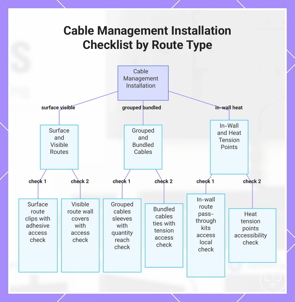
Installing Cable Management Accessories
Installing cable management accessories starts after cable connections and routing paths are confirmed. Cable management installation organizes visible and hidden cables to support cable accessibility, reduce cable tension, and keep connection paths easier to access later. The route choice is the main condition because cables may run inside the wall, on the wall, behind furniture, or along a surface.
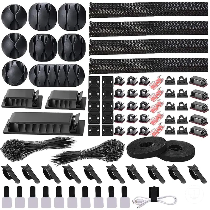
Visible clutter, cable tension, and inaccessible cable routes can make future adjustments more difficult. Cable clips, sleeves, ties, wall covers, raceways, and pass-through kits help organize cables when they match the route and access requirements. For broader planning and accessory selection, see cable management installation.
For in-wall routes, on-wall routes, behind-furniture layouts, and surface routing, cable-control accessories may be installed differently depending on access needs and mounting conditions. Cable accessibility should remain available where future cable changes, inspections, or device adjustments may be required.
Complex in-wall power work or structural modifications may require qualified help depending on local conditions.
Installing Cable Management Accessories uses the following route-based checklist to organize cable routing, cable organization, and future access.
- Surface route + cable clips: Use cable clips when cables follow a visible surface route; check adhesive limits and confirm access remains available.
- Grouped cables + sleeves: Use sleeves when multiple cables follow the same path; check cable quantity and confirm cables can still be reached if changes are needed.
- Bundled cables + ties: Use ties when cable organization requires grouping; check that ties do not create unnecessary tension or restrict access.
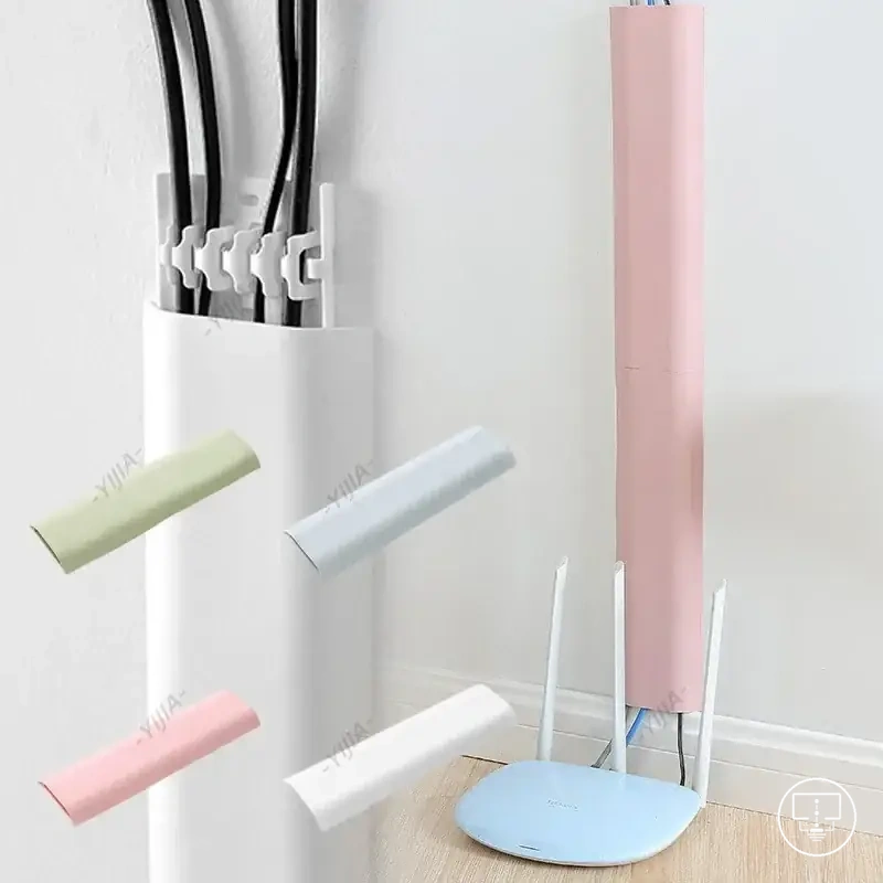
- Visible routing + wall covers or raceways: Use wall covers or raceways when cables remain visible along a wall; check that access remains practical after installation.
- In-wall route + pass-through kits: Use pass-through kits when the installation includes an in-wall route; check access points and follow local requirements where applicable.
- Heat or tension points: Keep cable routing away from locations that may create heat exposure or cable tension; check that cable accessibility is maintained after installation.
This chart organizes the route-based checklist for installing cable management accessories, grouped by surface visible routes, grouped bundled cables, and in-wall heat conditions.
Choosing In-Wall, On-Wall, or Adhesive Cable Routes
Choosing in-wall, on-wall, or adhesive cable routes depends on wall access, rental limits, appearance goals, and future device changes. Each cable route has a different level of permanence, visibility, and maintenance access. The main criteria are safety, permanence, and accessibility.
Route choice changes when wall access is limited or rental limits restrict permanent changes. An in-wall route may reduce visible cables but can involve power-cable restrictions and qualified help depending on local conditions. An on-wall route or adhesive route may be easier to reverse, but surface compatibility, cable quantity, and adhesive strength still need checking.
For renters, small rooms, or setups that change devices often, reversibility and maintenance access may matter more than the most hidden route.
Choosing In-Wall, On-Wall, or Adhesive Cable Routes compares route options by attribute, trade-off, and likely use case.
| Route option | Attribute | Trade-off | Best use case |
|---|---|---|---|
| In-wall route | Hidden route with wall access requirements | May involve power-cable restrictions, limited reversibility, and qualified-help needs | Setups where wall access is suitable and a more concealed route is appropriate |
| On-wall route | Visible route using wall covers or raceways | More visible than in-wall routing but usually easier to access for changes | Setups that need cable accessibility, maintenance access, or less permanent routing |
| Adhesive route | Removable route based on surface compatibility | Adhesive strength can vary by surface condition, cable quantity, and tension | Rental-limited setups or light surface routing where reversibility matters |
| Behind-furniture route | Low-visibility cable path with access limits | Can reduce visible cables but may make future device changes harder | Small rooms or stand-mounted setups where cables can remain reachable |
Fitting Cable Clips, Sleeves, Wall Covers, and Pass-Through Kits
Fitting cable clips, sleeves, wall covers, and pass-through kits starts with matching each cable-control part to its cable-control job. Cable clips guide a surface route, sleeves organize grouped cables, wall covers conceal visible cable paths, and pass-through kits organize route transitions. Route choice is the prerequisite before fitting begins.
Overfilled sleeves, stressed connectors, and poor adhesive surface preparation can reduce cable accessibility and make later adjustments harder. Clip spacing, sleeve capacity, cable bend limits, and adhesive surface condition should be checked before parts are secured. Complete each fitting stage with an access check.
For grouped HDMI, antenna, and audio cables, a sleeve may help organize the cable bundle while keeping connectors accessible. Power routing may require additional consideration depending on local requirements and installation conditions.
Fitting Cable Clips, Sleeves, Wall Covers, and Pass-Through Kits uses the following steps to organize cable-control parts while limiting cable stress and trapped access.
- Fit cable clips: Position cable clips along the chosen surface route, maintain suitable clip spacing, and check that cables remain accessible without excessive tension.
- Install sleeves: Place grouped cables into sleeves, confirm sleeve capacity is not exceeded, and verify that connectors are not compressed or stressed.
- Prepare the adhesive surface: Clean and inspect the adhesive surface before attaching wall covers or cable-control parts, then check that future access remains possible if removal is needed.
- Align wall covers: Fit wall covers or raceway covers along the cable path, confirm alignment with the route, and verify that removable access remains available where cable changes may occur.
- Position pass-through kits: Place pass-through kits at route transition points, check cable bend limits, and verify that access points remain reachable after installation.
- Perform a final access check: Review cable clips, sleeves, wall covers, and pass-through kits together, then confirm that cables remain accessible and free from unnecessary stress.
Keeping Cables Accessible for Future Setup Changes
Keeping cables accessible for future setup changes means leaving enough access after cable management is installed. Accessible cables, service loops, labeled cables, removable covers, spare cable length, and visible access points can make later device changes, troubleshooting, or cable replacement easier. The main condition is whether future setup changes may be needed.
Trapped cables, hidden adapters, and blocked replacement paths can make a simple cable change harder after installation. A removable route, clear labels, and service slack can help preserve cable access without overengineering the setup. Keep service access available where cables, adapters, or ports may need inspection.
If streaming, gaming, sound, or antenna devices may be added later, leave extra access around the related ports and cable routes.
Keeping Cables Accessible for Future Setup Changes uses the following checklist to preserve cable access, troubleshooting paths, and later replacement options.
- Service loops: Leave enough service slack where cables may need to move during future setup changes.
- Labeled cables: Label HDMI, antenna, audio, and power-related cables where identification may help troubleshooting.
- Removable covers: Use removable covers or access-friendly routes where cable changes may be needed.
- Spare cable length: Keep spare cable length where device position or adapter reach may change later.
- Access points: Keep visible access points available near ports, adapters, and cable junctions.
- Replacement paths: Preserve a route that allows cable replacement without sealing cables behind fixed parts.
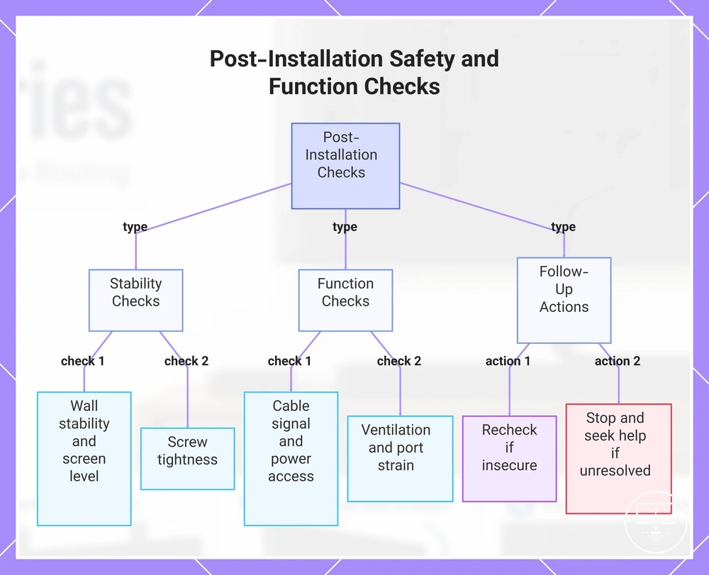
Final Safety and Function Checks After Installation
Final checks help confirm that installed TV setup accessories remain secure, functional, and accessible after installation. Post-install checks focus on both physical placement and connection performance so issues can be identified before regular use. The main verification areas are stability and signal function.
Physical movement, an uneven screen level, or loose hardware can affect setup reliability. Check wall stability, bracket movement, screen level, and screw tightness together to confirm a secure fit. If any part shifts, tilts, or feels insecure, perform a recheck before continuing.
Final safety checks should confirm cable signal, power access, ventilation, and port strain after all accessories are in place. A connection test can help verify that devices remain accessible and cables are not under unnecessary tension. If signal quality, ventilation, or port access appears restricted, further adjustment may be needed.
If a TV has been moved, tilted, or connected to a new device, repeat the relevant function checks and safety review. Small setup changes can affect cable signal, port strain, or future access.
When instability, blocked ventilation, or unreliable signal remains after a recheck, stop and review the installation condition. Qualified help may be appropriate when the cause cannot be identified or corrected safely.
The products below are useful examples for comparing available options. Before buying, check that the compatibility criteria, key features, and product details match your needs.
Final Safety and Function Checks After Installation uses the following checklist to verify stability, function, access, and follow-up actions.
- Wall stability: If movement is detected, recheck mounting support before continued use.
- Screen level and screw tightness: If the screen appears uneven or hardware feels loose, review alignment and fit.
- Cable signal and power access: If connections are unreliable or access is restricted, inspect routing and connection points.
- Ventilation and port strain: If airflow is limited or cables are under tension, adjust spacing or routing where appropriate.
- Cable visibility and future access: If cables cannot be reached for inspection or replacement, review access points and replacement paths.
This chart outlines the key stability, function, and follow-up checks to ensure TV setup accessories are secure and functional after installation.
Wall Stability, Screen Level, Cable Signal, and Power
Wall Stability, Screen Level, Cable Signal, and Power checks verify the main failure points after accessories are installed. This verification checklist tests whether the setup remains stable, level, connected, and accessible during normal use. Separate physical checks from functional checks.
A visual check alone may not identify bracket movement, cable signal issues, restricted outlet access, or changes in accessory fit. Checking movement, alignment, signal, and power together provides a broader setup review. Recheck the setup if anything shifts, disconnects, or becomes difficult to access.
If the TV has been moved, tilted, or connected to a new device, repeat the relevant stability check, level check, signal check, and power check before relying on the current setup condition.
Wall Stability, Screen Level, Cable Signal, and Power uses the following checklist to test different physical and functional conditions.
- Wall stability: If movement is noticed at the mounting area, a support issue may exist; review the mounting condition.
- Bracket movement: If the bracket shifts during normal adjustment, stability may be affected; inspect the secure fit.
- Screen level: If alignment appears uneven, accessory fit or positioning may need review; check the level alignment.
- Cable signal: If picture or audio performance appears inconsistent, a connection issue may exist; perform a signal check.
- HDMI handshake: If a connected device is not recognized where relevant, communication may not be complete; verify the connection state.
- Power reliability and outlet access: If power access is restricted or operation appears inconsistent, access or connection conditions may need review.
- Cable tension: If cables pull against ports or accessories, port strain may increase; adjust the cable path where appropriate.
- Accessory fit: If an accessory blocks access or sits unevenly, the installation condition may require further inspection.
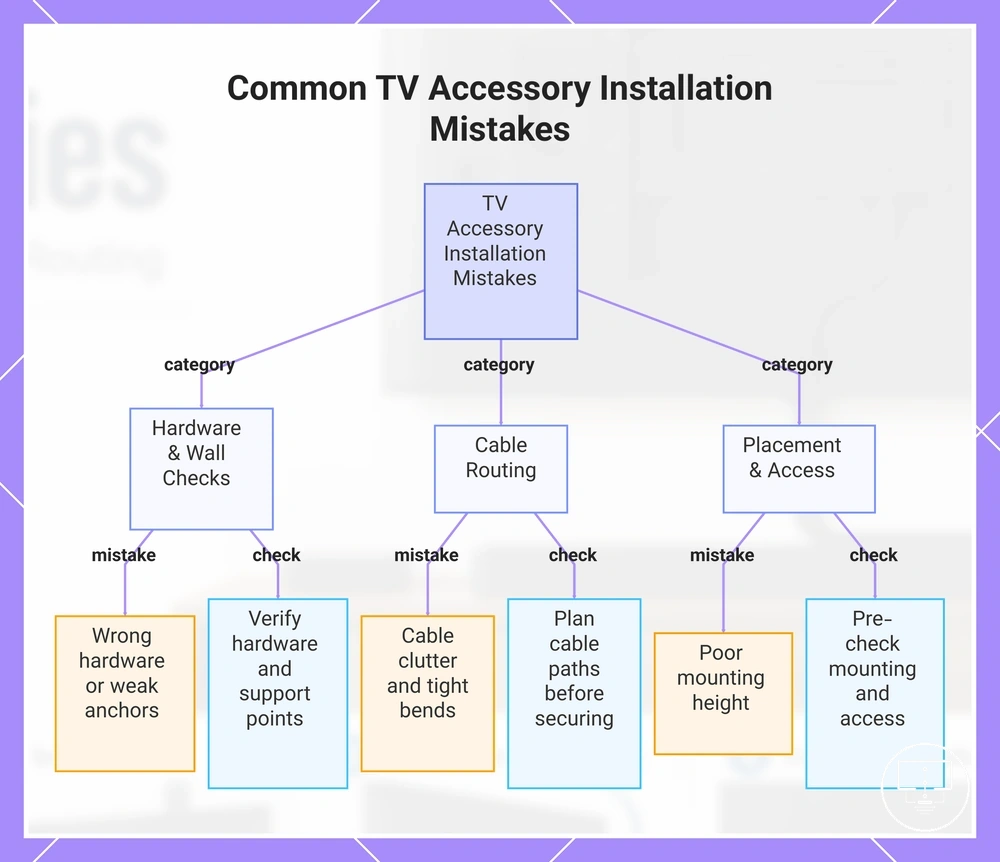
Common TV Accessory Installation Mistakes
Common TV accessory installation mistakes often come from missed verification steps rather than defective accessories. The most common patterns involve hardware selection, mounting support, cable routing, and access planning. Many installation mistakes begin with skipped checks, wrong hardware, blocked access, and rushed routing.
Hardware and wall-check mistakes can create fit, support, or positioning problems later in the installation process. Wrong hardware, weak anchors, missed studs, and incorrect screws may reduce confidence in the installation if they do not match the wall or mounting conditions. Checking hardware compatibility and support points before installation can help prevent these fitting mistakes.
Cable-related setup mistakes often appear after the TV and accessories are already in place. Cable clutter, tight bends, blocked ports, and inaccessible connections may make future adjustments or device changes harder. When the issue comes from cable routing or placement choices, it is usually an installation correction rather than a deeper accessory problem.
In wall-mounted or tight-space setups, access limitations may become more noticeable after installation is complete. Poor mounting height, limited outlet access, or blocked ports can affect viewing comfort and future device connections.
Common TV Accessory Installation Mistakes uses the following checklist to help prevent recurring installation errors. If the setup remains unreliable after correcting installation-related conditions, the issue may belong to broader installation problems rather than installation technique alone.
The products below are useful examples for comparing available options. Before buying, check that the compatibility criteria, key features, and product details match your needs.
- Hardware: Wrong screws, wrong hardware, or weak anchors may not match the mounting condition; verify hardware suitability before installation.
- Hardware: Missed studs or unsupported mounting points may affect stability; confirm support locations before fixing hardware.
- Placement: Poor mounting height may reduce viewing comfort; check position before final installation.
- Placement: Screen level issues may appear when alignment checks are skipped; verify level alignment before tightening hardware.
- Cable routing: Cable clutter may reduce access and organization; plan cable paths before securing accessories.
- Cable routing: Tight bends may increase cable strain; maintain suitable cable routing where space allows.
- Access: Blocked ports may limit future device connections; check port access before final positioning.
- Access: Inaccessible connections or hidden power issues may complicate later checks; keep key connection points reachable where possible.
This chart shows the main categories of installation mistakes and the corresponding checks to prevent them.
Incorrect Hardware, Wall Checks, or Mounting Height
When physical installation problems appear, incorrect hardware, missed wall checks, or mounting height mistakes are often part of the cause. These conditions can affect support, alignment, and viewing position even when the accessories appear suitable. If these signs appear during installation, stop and verify hardware and installation conditions before continuing.
Support problems should be rechecked rather than covered over with additional accessories or adjustments. Wrong screw length, missing washers, weak anchors, and skipped stud checks can create installation concerns that depend on the wall, hardware, and mounting conditions. If support conditions seem uncertain, stop, verify hardware, or seek help before proceeding.
In setups with uneven bracket marks or an unsuitable surface choice, alignment and support concerns may become visible during installation. Rechecking the surface and mounting height can help identify whether the issue comes from placement, support, or hardware selection.
Incorrect Hardware, Wall Checks, or Mounting Height uses the following checklist to diagnose support, alignment, and viewing-related mistake patterns.
- Wrong screw length: May affect bracket fit; stop and verify hardware compatibility.
- Missing washers: May influence bracket fit or spacing; recheck hardware requirements before continuing.
- Weak anchors: May reduce support quality on some surfaces; recheck the surface and anchor suitability.
- Skipped stud checks: May increase surface risk during mounting; verify support points before adding more accessories.
- Uneven bracket marks: May lead to alignment concerns; perform a level check before proceeding.
- Unsuitable surface choice: May not provide the expected support conditions; stop and reassess the mounting surface.
- Mounting height mismatch: May affect viewing comfort or screen position; review placement before finalizing the installation.
Cable Clutter, Tight Bends, and Inaccessible Connections
When signal access, device access, or maintenance becomes difficult after installation, cable clutter, tight bends, and inaccessible connections may be contributing factors. These cable routing errors can affect access and cable condition, although not every signal issue comes from routing alone. The main risk is increased cable strain and reduced access for future changes.
Tight HDMI bends, overloaded sleeves, and hidden adapters can create cable access problems that are difficult to notice during installation. Connector strain may develop when cables are forced into limited space, while overloaded sleeves can make individual cables harder to reach. If these conditions are present, perform a cable route and access check before making further changes.
In a wall-mounted TV setup, blocked rear ports can make later correction harder because cables and adapters may be difficult to reach after installation is complete.
Cable Clutter, Tight Bends, and Inaccessible Connections uses the following checklist to diagnose common cable-routing mistake patterns.
- Symptom: Intermittent connection or access concern; Likely routing issue: tight HDMI bends causing connector strain; Check: inspect cable routing near the port.
- Symptom: Excess cable buildup; Likely routing issue: overloaded sleeves contributing to cable clutter; Check: review cable grouping and access.
- Symptom: Difficult maintenance access; Likely routing issue: hidden adapters behind equipment; Check: verify adapter visibility and reachability.
- Symptom: Port access is restricted; Likely routing issue: unreachable ports caused by cable placement; Check: confirm access before repositioning equipment.
- Symptom: Cable path confusion; Likely routing issue: mixed cable paths increasing access problems; Check: review cable organization and identification.
- Symptom: Future cable changes are difficult; Likely routing issue: cable covers that cannot be reopened easily; Check: confirm that cable access remains available.